

- Thread starter
- #1
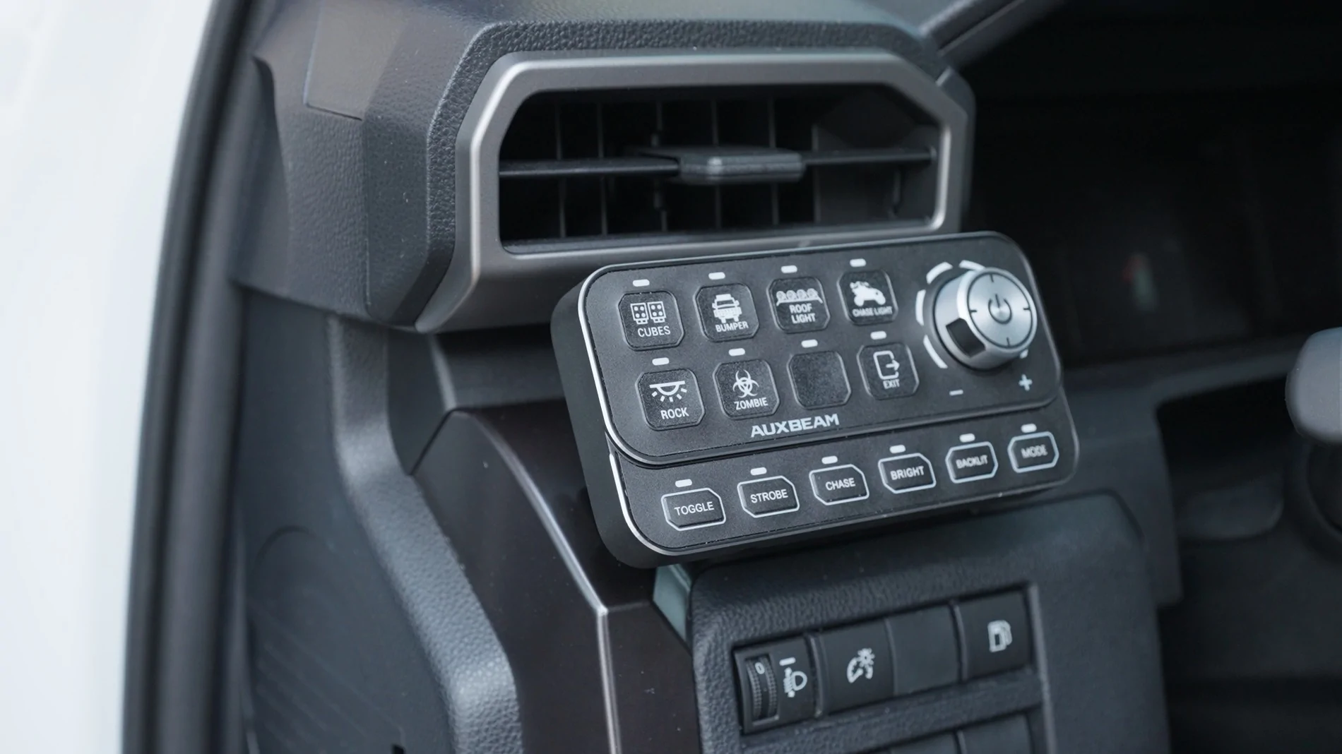
I am in the process of installing more exterior lights and knew the best way to do this was installing a multi-gang switch panel instead of having to deal with a rats nest of wire, relays, and switches every time I add a new lights or accessory. Luckily for me Auxbeam offered to send out their brand new Auxbeam KS-80 Knob switch panel.

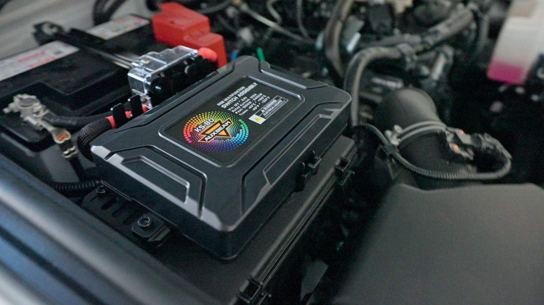
I'm not going to go into details about the features of the KS-80, instead I am want to show the actual install process since this will apply to most users and work with any Auxbeam Switch Panel. I do believe this is the cleanest way to install a switch panel without buying extra custom mounts.
PRODUCTS USED:
I used all included brackets that came with the switch panel except I did make some small modifications to both the power control unit and the switch panel bracket to get them positioned exactly where I wanted.
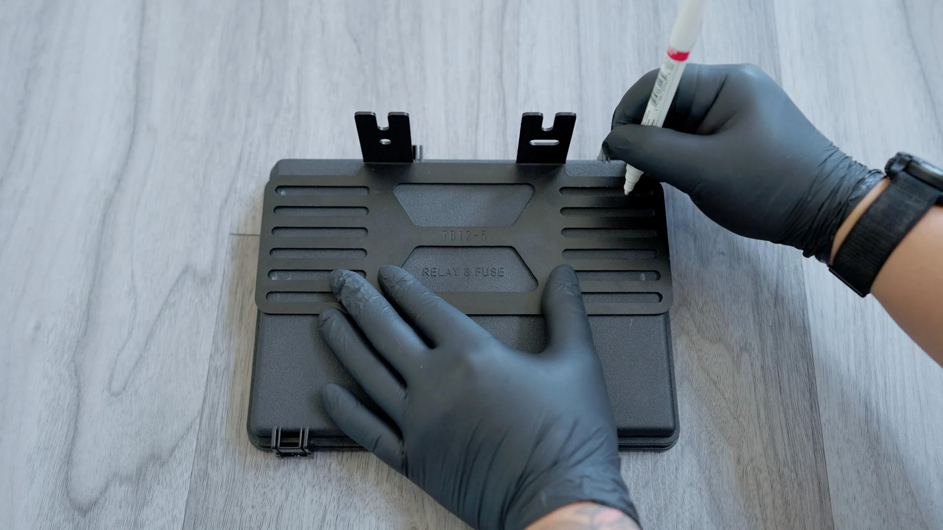
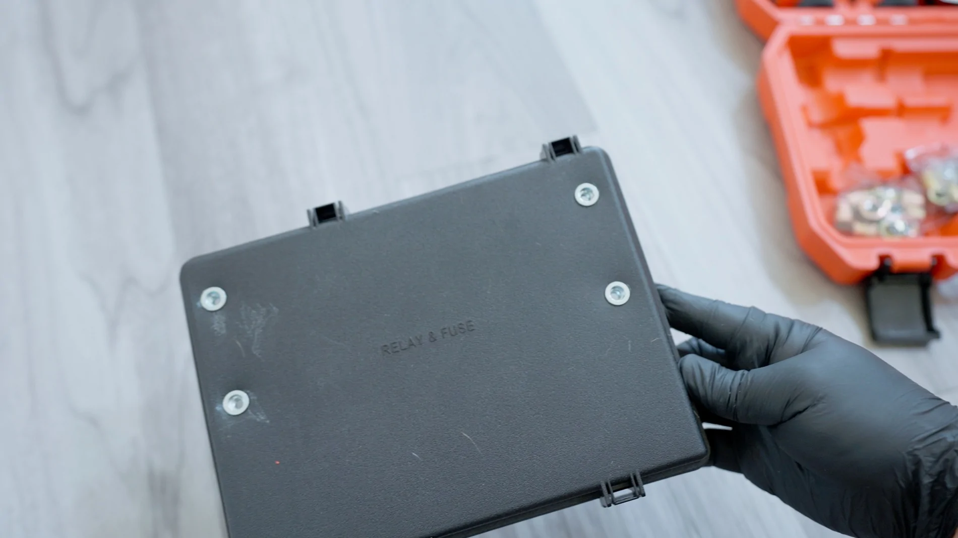
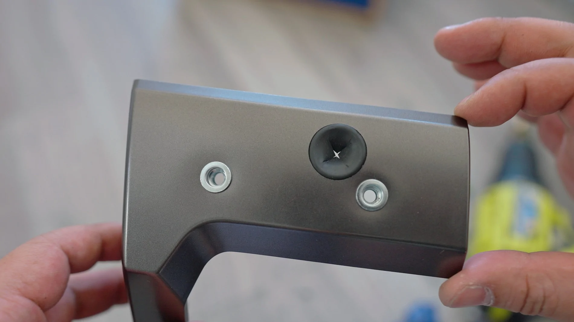
I first marked out holes to drill in the fuse cover to position the KS-80 in the center of the cover when mounted. At this point I drilled out holes in the fuse cover and installed M6 rivnuts. This is a bit overkill, you could just use nuts and bolts, but I thought the rivnut would look better and make install easier since you can just tighten the bolts from the top instead of dealing with nuts on the under side of the fuse cover.
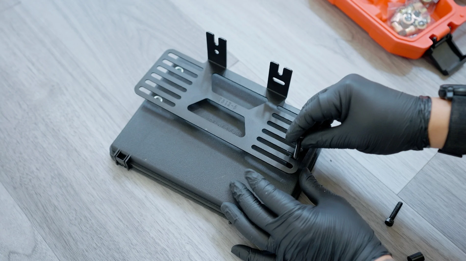
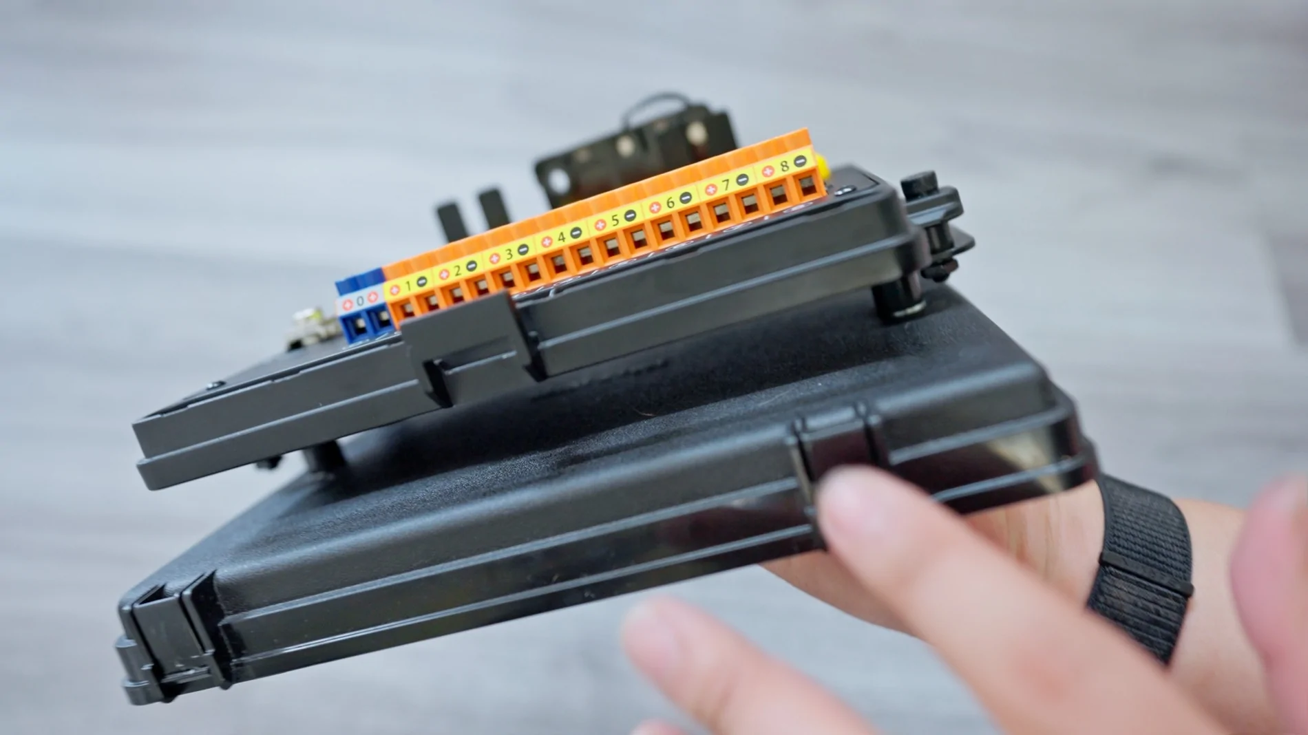
When installing the bracket onto the fuse cover, I used m6 spacers for each bolt to raise the bracket about an inch above the actual fuse cover. This creates a gap that will allow you to route your power, ground, and accessory wires underneath the KS-80 when installing in the engine bay. This is the trick to a clean install instead of having wires coming out in all directions. Routing the wires underneath will hide most of your wiring.
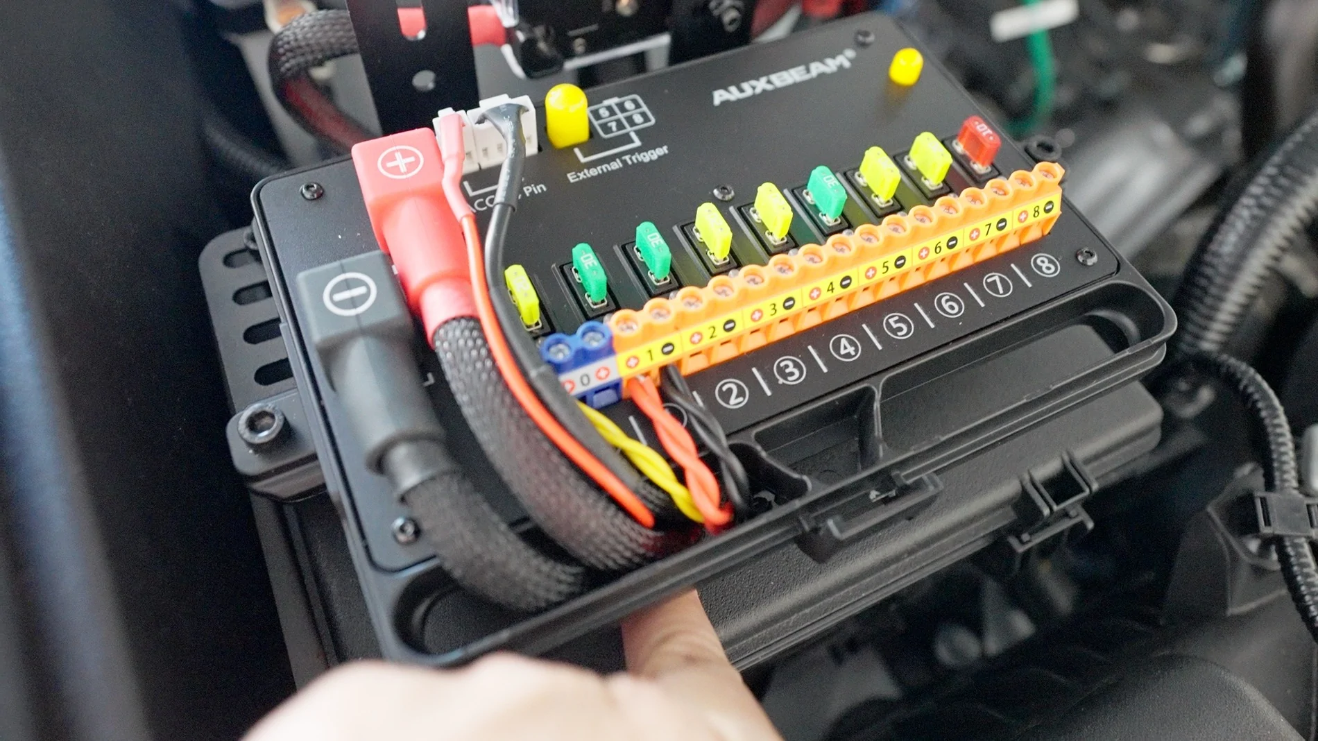
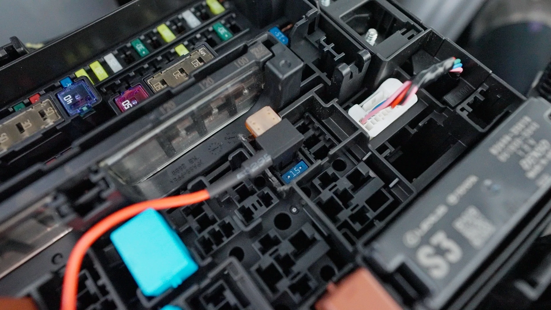
Most switch panels need to be wired to a "trigger" wire to signal the unit to only turn on when you power up your vehicle. Conveniently there are switched fuse slots directly underneath where you are mounting the Auxbeam KS-80. I chose to use an open/unused fuse slot which is located in the middle in between two used fuse slots.
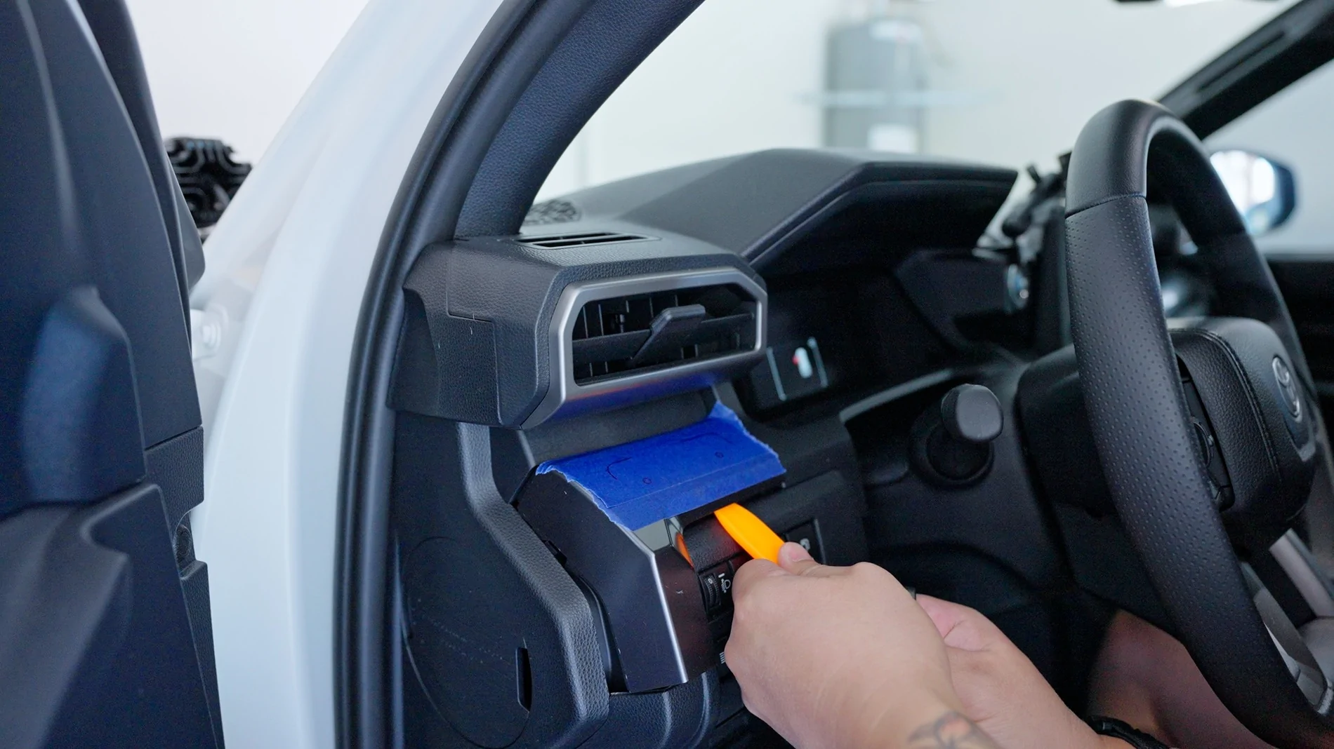
The actual switch panel install was pretty self-explanatory. All I did was mark the dash trim where I wanted to mount the switch panel. This dash trim easily pops out with a trim tool and gives you a perfect location that is easy to reach and out of the way.
I wanted to use the rivnut tool again so I followed the same process as the fuse cover to get these installed. I also drilled a larger hole that will be used to pass the switch panel wire through the trim and into the footwell where it will connect to the power unit side of this switch. I also inserted a grommet in this hole to keep everything clean.
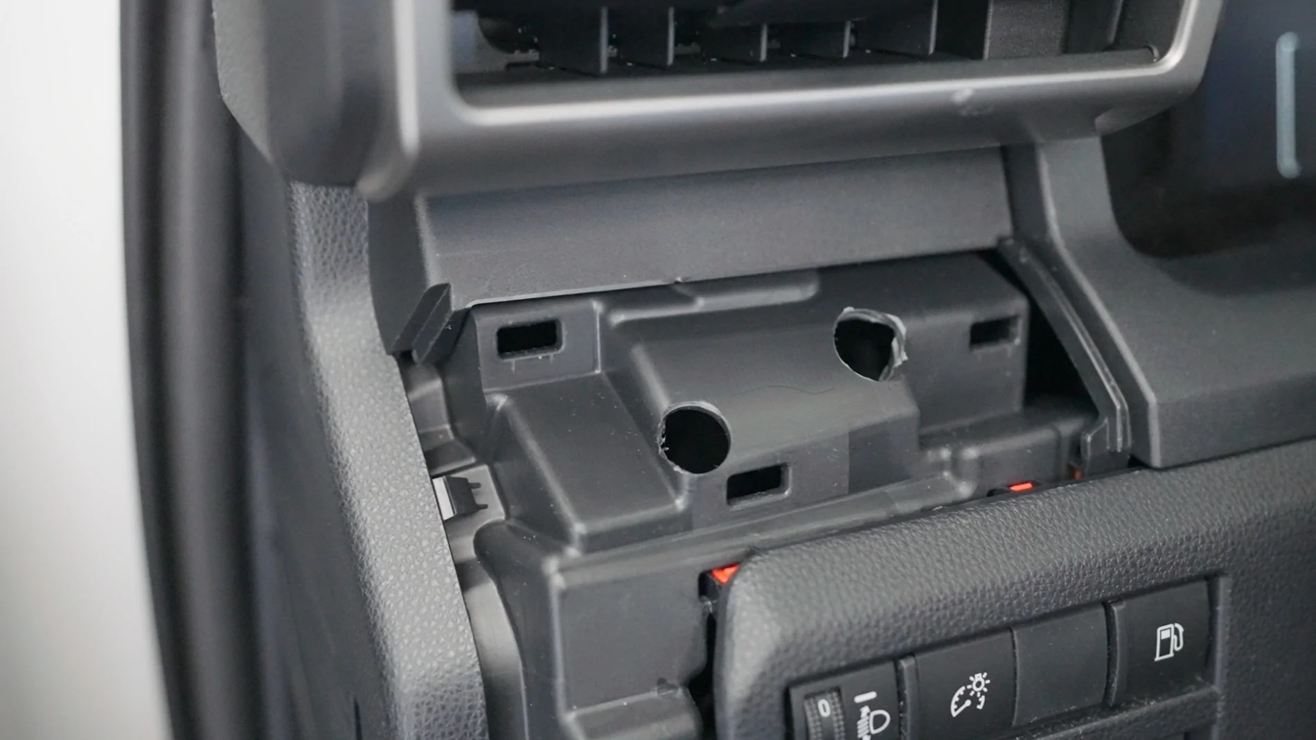
You will need to notch the plastic underneath the trim piece. This is required so you can route the switch panel wire and so there is enough space to fit the rivnuts that you installed on the trim. This was really easy to do. Basically just mark the areas that need to be notched, drill a small hole, then expand that hole with a step drill bit. This will provide the spacing you need to snap the trim piece back in.
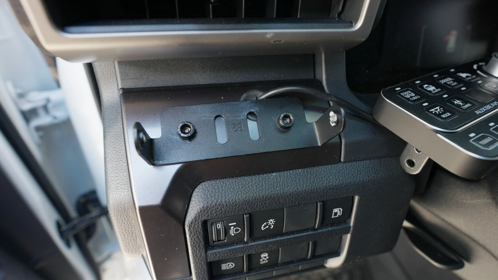
Once you have the trim piece back in place, you can feed the switch panel side of the wire through the grommet and bolt the bracket down to give you a sturdy location for the switch panel inside the cabin.
Hopefully this guide as helped anyone trying to install a switch panel in our 6th Gen 4Runners. I would appreciate any new subscribers on my YouTube Channel at EverydayFred.
Sponsored
Last edited:

