

- Thread starter
- #1
Hey everyone,
I installed an Auxbeam RA80 in my 4Runner this weekend, and as a complete novice in automotive wiring, I couldn’t find a comprehensive guide on this install that answered all my questions. Hopefully, I can cover those details in this thread.
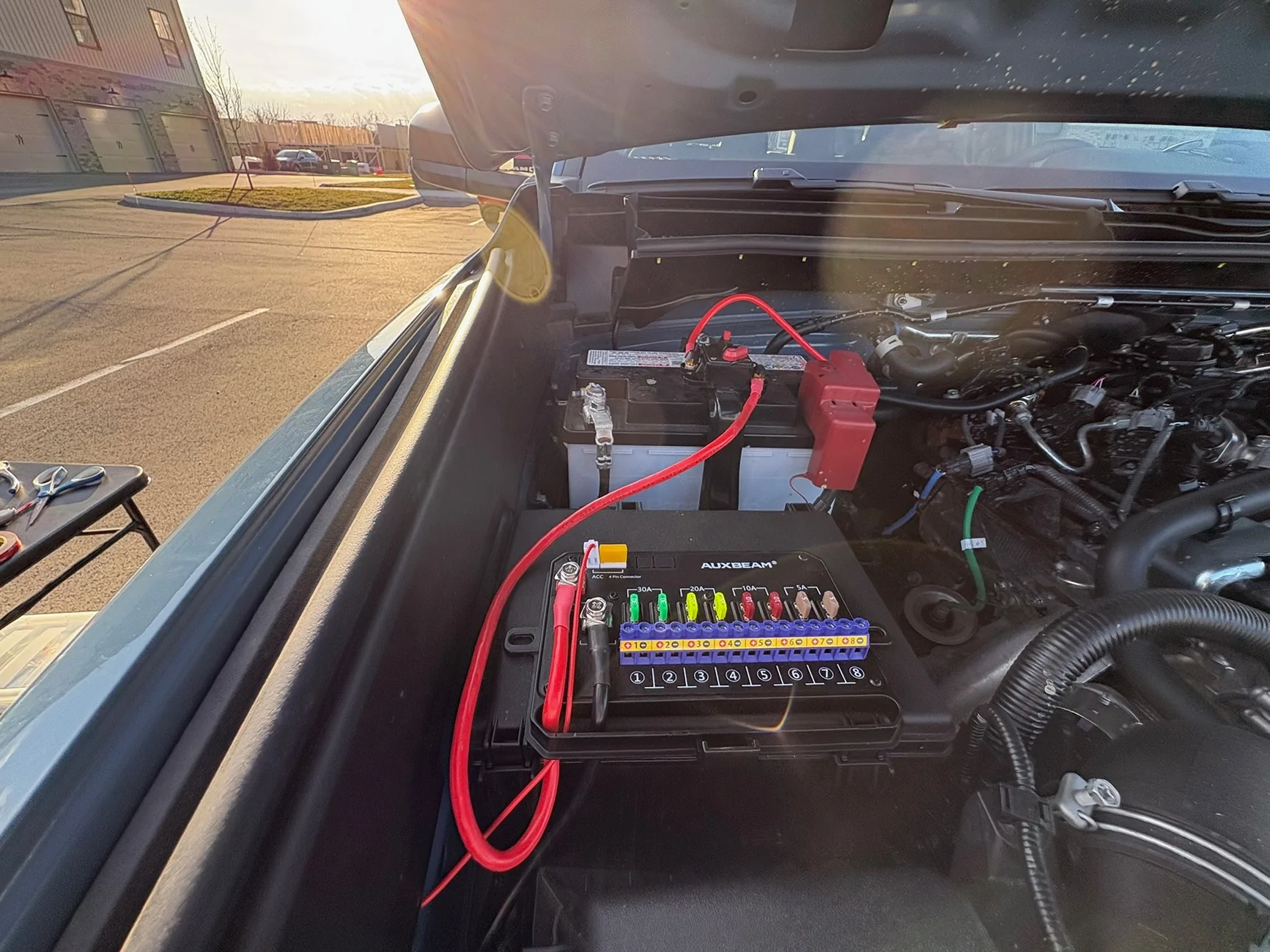
1. Mounting the control box
I mounted the control box to the top of the fuse box on the passenger side with 3M VHB, and mounted the circuit breaker on the battery bracket.

2. Fuse Tap
Most videos on this system will tell you to tap into an ECU fuse in either the engine bay passenger fuse box or the fuse box on the passenger side in the cabin. The goal of this fuse tap is to make the switch panel dependent on the ignition being on. I tried both of these positions with no luck. The engine bay fuse box on the passenger side physically did not fit a fuse tap, and when I tapped into a fuse in the cabin fuse box, my car threw a bunch of codes. Thankfully, I was able to get the codes to go away by disconnecting the negative terminal of the battery.
My Solution:
I went into the fuse box in the engine bay on the drivers side and tested all the empty slots with a multimeter and found one location that only received power when the ignition was on. See the picture below:

I had to extend the provided wire, and I ran it around the front of the engine bay. When you get to the fuse box, you’ll see a small slit in the wiring loom leading into the fuse box. I was able to slide the wire through that slot and splice it into the fuse tap there.
Make sure you put 2 fuses in the fuse tap for it to work properly. Being as inexperienced as I was, I didn’t realize that’s how those work.
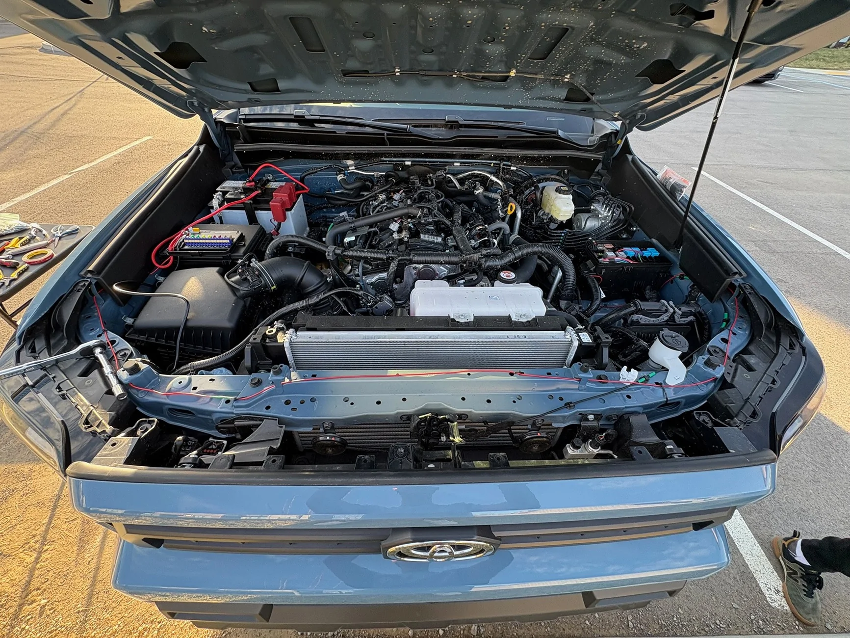
3. Running the control panel cable into the cabin
I ran the braided 4 pin cable around the front of the engine bay, following the same path as the signal wire above. There is a rubber grommet about 1/3 of the way down the firewall. I was able to pull that off just enough to slide the cable through, and was able to reseat the grommet smoothly. I added a little sealant just to be safe. For this wiring path, you will need to extend the 4-pin cable that comes with the system. I was able to get a 4ft extension for 15 bucks on Amazon, which gave me plenty of room to work with. On the inside of the car, you’ll find the cable drops down above the brake pedal.
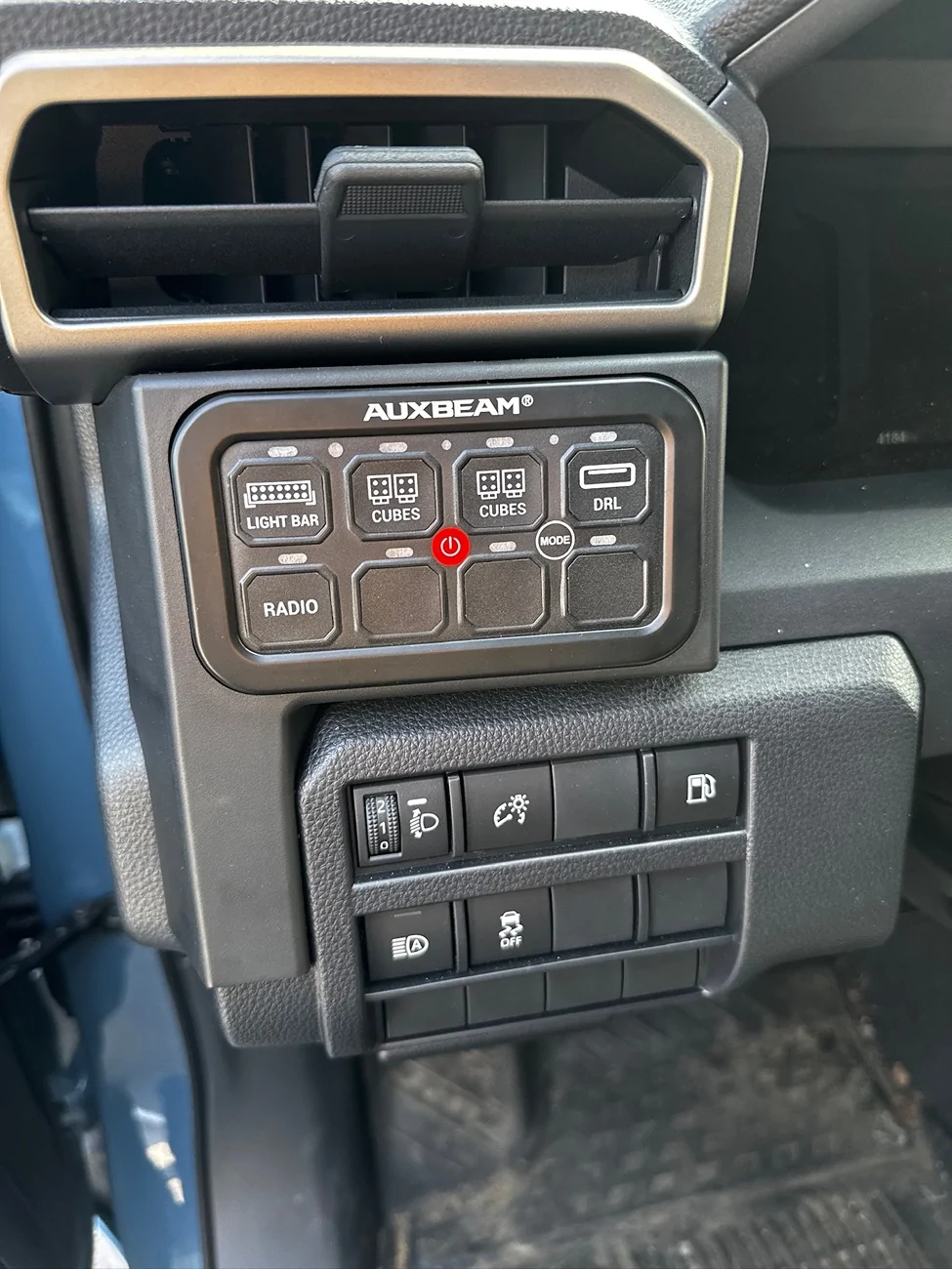
4. Mounting the control panel
I used a mounting panel from Cali raised. It fits this switch panel perfectly. You will need to remove two pieces of trim, which pop off easily with a trim removal tool.
You will need to drill a hole to fit the 4 pin cable coming out of the switch panel. I drilled it on the flat spot in the center. There are some wires behind that, so make sure to reach in through the side and make sure you’re not drilling into anything.
The control panel bolts right into the bracket from Cali raised, and the whole setup clicks right in—make sure to transfer the plastic clips from the original trim piece.
From there, you just need to plug the panel into the braided cable, tie up the excess wire, and snap all the trim pieces back into place.
This is by no means actual mechanical advice, but hopefully this will be helpful for anyone starting in the same place I did.
I installed an Auxbeam RA80 in my 4Runner this weekend, and as a complete novice in automotive wiring, I couldn’t find a comprehensive guide on this install that answered all my questions. Hopefully, I can cover those details in this thread.
1. Mounting the control box
I mounted the control box to the top of the fuse box on the passenger side with 3M VHB, and mounted the circuit breaker on the battery bracket.
2. Fuse Tap
Most videos on this system will tell you to tap into an ECU fuse in either the engine bay passenger fuse box or the fuse box on the passenger side in the cabin. The goal of this fuse tap is to make the switch panel dependent on the ignition being on. I tried both of these positions with no luck. The engine bay fuse box on the passenger side physically did not fit a fuse tap, and when I tapped into a fuse in the cabin fuse box, my car threw a bunch of codes. Thankfully, I was able to get the codes to go away by disconnecting the negative terminal of the battery.
My Solution:
I went into the fuse box in the engine bay on the drivers side and tested all the empty slots with a multimeter and found one location that only received power when the ignition was on. See the picture below:
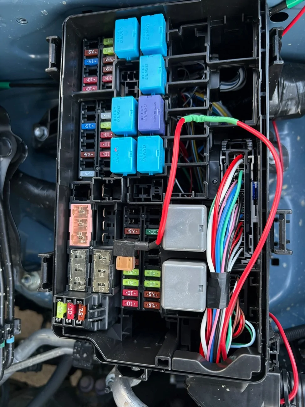
I had to extend the provided wire, and I ran it around the front of the engine bay. When you get to the fuse box, you’ll see a small slit in the wiring loom leading into the fuse box. I was able to slide the wire through that slot and splice it into the fuse tap there.
Make sure you put 2 fuses in the fuse tap for it to work properly. Being as inexperienced as I was, I didn’t realize that’s how those work.
3. Running the control panel cable into the cabin
I ran the braided 4 pin cable around the front of the engine bay, following the same path as the signal wire above. There is a rubber grommet about 1/3 of the way down the firewall. I was able to pull that off just enough to slide the cable through, and was able to reseat the grommet smoothly. I added a little sealant just to be safe. For this wiring path, you will need to extend the 4-pin cable that comes with the system. I was able to get a 4ft extension for 15 bucks on Amazon, which gave me plenty of room to work with. On the inside of the car, you’ll find the cable drops down above the brake pedal.
4. Mounting the control panel
I used a mounting panel from Cali raised. It fits this switch panel perfectly. You will need to remove two pieces of trim, which pop off easily with a trim removal tool.
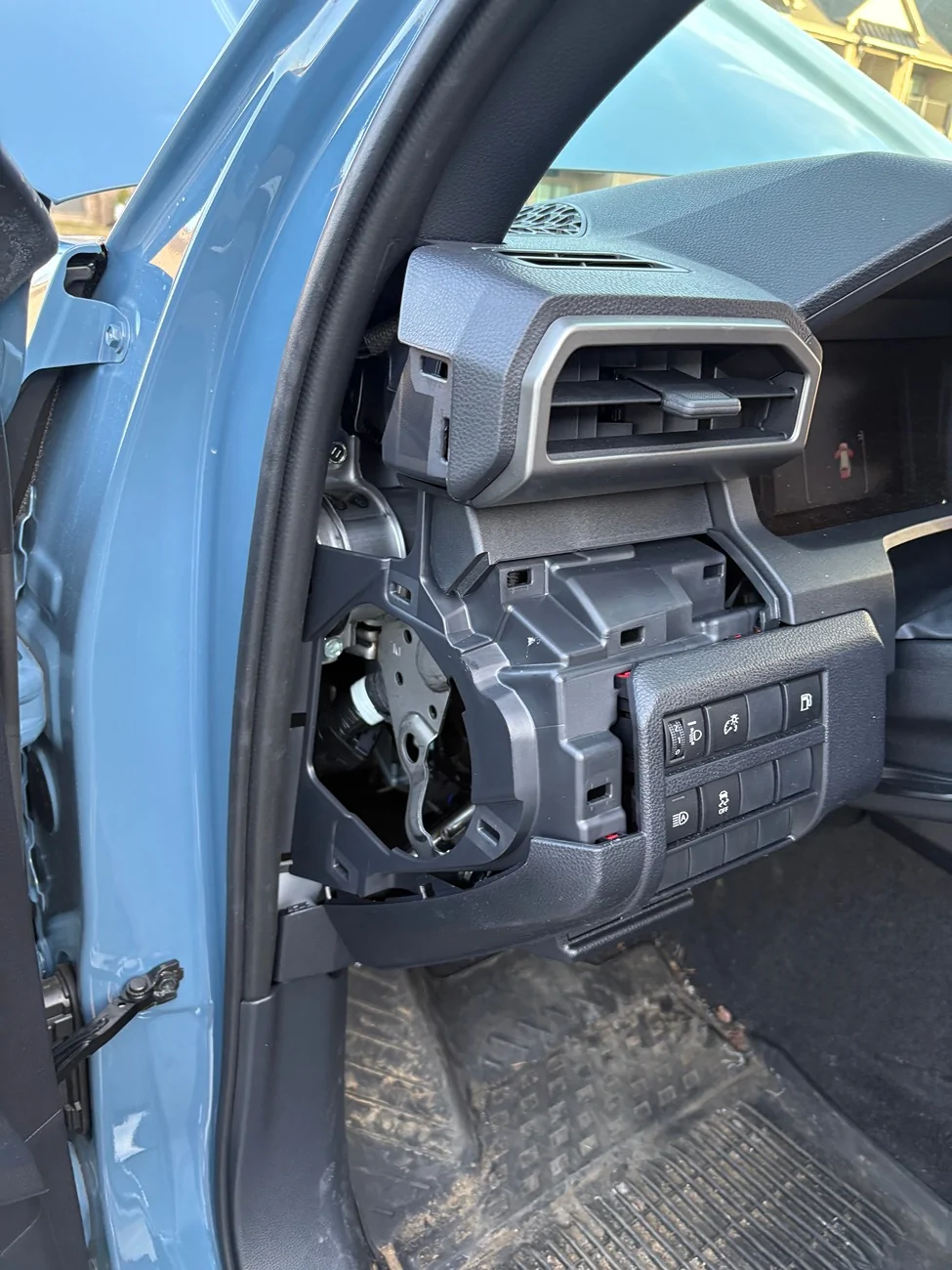
You will need to drill a hole to fit the 4 pin cable coming out of the switch panel. I drilled it on the flat spot in the center. There are some wires behind that, so make sure to reach in through the side and make sure you’re not drilling into anything.
The control panel bolts right into the bracket from Cali raised, and the whole setup clicks right in—make sure to transfer the plastic clips from the original trim piece.
From there, you just need to plug the panel into the braided cable, tie up the excess wire, and snap all the trim pieces back into place.
This is by no means actual mechanical advice, but hopefully this will be helpful for anyone starting in the same place I did.
Sponsored


